Electronics corrosion simulation apps are the focus of a new case study from the Technical University of Denmark’s Centre for Electronic Corrosion, or CELCORR, which says it is using models to flag humidity-related risks in printed circuit boards before a design reaches the field. The work matters for high-voltage electronics used in examples such as electric vehicles, wind systems and data centers, where an intermittent board fault is a bad time to discover that moisture had a vote.
The account comes from COMSOL’s May 2026 user story, later carried as sponsored or product material elsewhere. It describes an engineering project, not independent validation that the apps can determine the cause of a real-world failure or reduce failure rates.
CELCORR’s premise is straightforward: humidity can condense on electronic surfaces, creating conditions for corrosion. According to the case study, that process can produce leakage current and, through electrochemical migration, conductive dendrites that short parts of a circuit. Ansys, in separate vendor educational material, also lists corrosion, contamination-related current leakage and electrochemical migration among possible electronics failure mechanisms.
How do electronics corrosion simulation apps test a PCB?
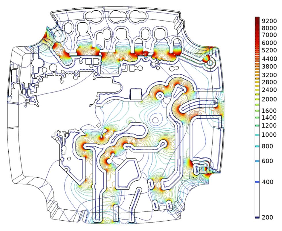
Researchers built a simplified PCB model that matched their test boards and the design of a device from an industry partner, COMSOL said. They added a water-film layer as a representation of relative humidity, then recalculated the model while changing the layout and geometry, spacing between electrodes, water-film thickness and the film’s conductivity.
One CELCORR illustration describes a 10-micrometer condensation film on an example PCB. The model calculates electrochemical leakage current between board features under the assumed wet condition. Rajan Ambat, a DTU professor who leads CELCORR, said the resulting current provides an indication of whether the PCB could be affected.
That is design screening, not a magic postmortem. A simulation can test whether a particular combination of moisture and geometry makes a proposed mechanism plausible. It cannot, on its own, establish what happened to a failed unit in the field.
What still has to happen after an electronics failure?
Failure analysis starts with the evidence that the model cannot conjure up: the observed fault, operating environment, location of the failure on the PCBA, and records from design, manufacturing, testing and field use. Ansys describes failure analysis as examining the failure site, mechanism and environment; it distinguishes that device-focused work from broader root-cause analysis.
- Localize the fault to a board area, component or interconnect.
- Collect environmental exposure and manufacturing information alongside test and field records.
- Use the model to compare credible humidity, water-film and layout scenarios.
- Verify the suspected corrosion mechanism with physical evidence before changing the design or process.
Epec, a manufacturer, similarly advises that simulations or experiments may be needed to confirm a hypothesis and that investigators should verify a suspected cause rather than jump to one. That caveat is doing real work here: corrosion may be one explanation, while a board can also fail through material, thermal, mechanical or contamination problems.
COMSOL said in June that the DTU project appears in its 2026 customer-story publication. The company describes its software as an environment for physics-based models and simulation apps. CELCORR’s reported work shows how such software can rank corrosion risks early in a design cycle; proof still belongs to the failed hardware and the evidence around it.
This story draws on original reporting from IEEE Spectrum.